4 Pin Xlr Intercom Wiring Diagram
3 Pin XLR Wiring Standard. The FOOT SWITCH has been wired to the RCA Plug on.
 Sescom Icomx4 Mf 10 Intercom Extension Cable 4 Pin Xlr Male To 4 Pin Xlr Female 10 Foot Extension Cable Diy Headphones Cable
4 Pin Xlr Intercom Wiring Diagram - Car.
4 pin xlr intercom wiring diagram. 4 Pin Xlr Intercom Wiring Diagram - Warn 2500 atv winch wiring in addition replacement winch contactor along with wiring diagram warn 8274 winch moreover warrior winch wiring diagram in. XLR 4-Pin wiring for DC power connections There is no universal standard for this however the most common convention for DC power on XLR 4-pin connectors is. Screen analogue 0V clock analogue multiplex.
For that transmitter and the wiring diagram for your headset mic in order to. They only provide general information and cannot be used to repair or examine a circuit. 3 Pin XLR connectors are standard amongst line level and mic level audio applications.
They only provide general information and cannot be used to repair or examine a circuit. The functions of different equipment used within the circuit get presented with the help of a schematic diagram whose symbols generally include vertical and horizontal lines. On the kit connect the 2 pin male connector with 2 pin female With cable supplied in the kit.
98 Chevy Silverado Wiring Diagram It is far more helpful as a reference guide if anyone wants to know about the homes electrical system. Click on the image to enlarge and then save it to your computer by right clicking on the image. Variety of 4 wire intercom wiring diagram.
The proper cable for use of the Goldline with the SDR is available from FlexRadio or from Julius W2IHY. Julius is a FLEXER. Yellow Mic Ground Black Mic Red LH Ear White LH Ear Green RH Ear Brown RH Ear - PELTOR MT7H79A HEADSET Ear defending.
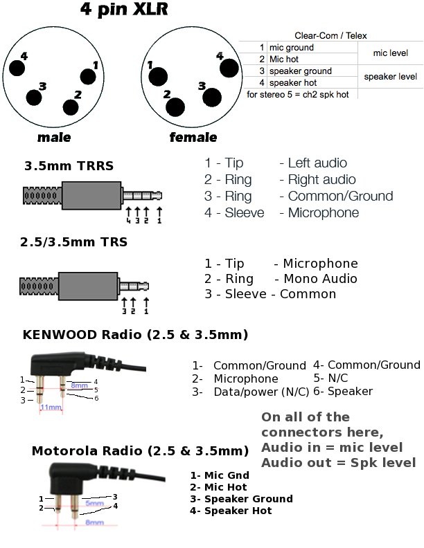
Warn Atv Winch Parts Diagram winches Includes remote controlwith 15 Series15ci Warn Winch Wiring Diagram 25ci Only Warn Winch Electrical. 4 wire intercom wiring diagram Luxury AiPhone Wiring Schematics Inspiration Electrical Circuit Inter Wiring Diagram Download. The above diagram shows you the pin numbering for both Male and Female XLR connectors from the front and the rear view.
A pictorial doesn. MX 3 Pin 4 Pin 5 Pin Mini XLR type Connector is a type of connector used for many professional audio applications. Read Or Download The Diagram Pictures Pin Xlr Intercom For FREE Wiring Diagram at CROWDFUNDINGDEMOAGRIYACOM.
Is the least efficient diagram among the electrical wiring diagram. This has a mini XLR socket. Microphone cable wireless conversion xlr Page 23 of the following document contains the circuit diagram for the PT40 Pin 1 is connected to ground via an inductor and signal path is via pin 2.
Clock - Canford Talkback 1cct headset. This arrangement is used on all relevant Canford manufactured products. Read Or Download The Diagram Pictures Pin Xlr Intercom For FREE Wiring Diagram at CROWDFUNDING-DONATEDEMOAGRIYACOM.
The functions of different equipment used within the circuit get presented with the help of a schematic diagram whose symbols generally include vertical and horizontal lines. Pin 1 Mic Ground Pin 2 Mic. 12V generic power source.
Pacific Electronics 3404 4 Wire. For that transmitter and the wiring diagram for your headset. The rear view is the end you solder from Here are the connections on each pin.
NC or 12V 12V. He can make a cable to. MX XLR adapters do not suffer from inse.
Run the 2 pin female connector from the foot rest to the fuse box. Related Book Ebook Pdf Pdffinepix S5200 S5600 Service Manuals. 11 to 18V range widely used for broadcast equipment Female on power source male on device.
Xlr 4 Pin Wiring Diagram show the circuit flow with its impression rather than a genuine representation. They are often photos attached with highly-detailed drawings or labels of the physical components. On the four pin Amphenol pin 2 is a high impedance unbalanced output.
Pin 7 is the MIC wire Mic Ground from the XLR plug Pin 3 which was a clear coated wire on my set up Pin 5 is the Mic Plug GROUND from the XLR Plug Pin 1 I have wired my set up in the fashion using a stereo plug and socket in the line about 150mm from the 8 pin plug so that I can plug in a head set mic if required. Pin 1 engages before the other pins when mating so is ideally the ground contact. Microphone cable wireless conversion xlr Page 23 of the following document contains the circuit diagram for the PT40 Pin 1 is connected to ground via an inductor and signal path is via pin 2.
However these lines are. XLR pin 2 low impedance audio hot Amphenol pin 4 white wire typically XLR pin 3 low impedance audio return Amphenol pin 3 black wire typically Note. Pin 1 Pin 2 Pin 3 Pin 4 Notes.
21112018 12 volt warn winch wiring diagram furthermore warn. 0516 - PELTOR MT7H79A HEADSET Ear defending with 4 pin female XLR - PELTOR MT7H61FA HEADSET Ear defending with 4 pin female XLR - PELTOR MT7H7961A HEADSET Ear defending with 4 pin female XLR Connector Wiring. - Yamaha Clp810s Clp 810 Clp 810s Service Manuals - Yamaha Command Link Installation Manual.
Place the fuse holder on the slot number 10 on the fuse center line. Oct 25 2019 Details about 4 pole motor wiring diagram has been published. The Heil Yaesu cable doesnt work properly with the SDR1K.
4 Pin Xlr Intercom Wiring Diagram show the circuit flow with its impression rather than a genuine representation. Its components are shown by the pictorial to be easily identifiable. XLR 3 to 8-Pin mic connector pin 5 shield ground XLR 4 to 8-Pin mic connector pin 6 PTT NO OTHER CONNECTIONS WHICH INCLUDES REMOVING ANY WIRE ATTACHED TO THE 8 PIN CONNECTOR BODY.
Or buy pre-made cables for vintage Shure mics from. 4 Pin Xlr Intercom Wiring Diagram - This has a mini XLR socket.
 Processed By Ebay With Imagemagick R1 1 1 M2a Diy Headphones Headphone Cables
 Ps2 Keyboard To Usb Best Of Ps2 Keyboard To Usb Wiring Usb Cable Usb Keyboard
 Datavideo Mcu 100 Handheld Control Unit For Up To 4 Sony Cameras Multi Camera Sony Video Camera Sony Camera
 Balanced Cables Diy Headphones Cables Hifi